Below is a list of modifications made by the previous first owner of Harried Potter. The words below are written entirely by him. Aside from being delightfully entertaining, his commentary gives an idea of how we knew this was an exceptional little boat.
Carpeted Galvanized Tire Fenders with Non-Slip Steps

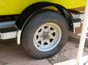
When I first purchased Harried Potter, I noted that there was a manufacturer’s defect with the trailer. Specifically, Pacific Trailer had mounted merely 7" wide fenders over the wheels, rather than the proper 9" fenders necessary to adequately cover its 14"/15" tires. In point of fact, I noted that the trailer steps actually had holes pre-drilled for wider fenders, but Pacific Trailer had evidently decided to ignore them and pinch pennies by installing narrower, cheaper fenders instead.
I therefore determined to replace the narrow fenders as soon as possible. I found some 9" wide galvanized steel fenders on the web that in all other respects seemed to match, and immediately placed an order. When they arrived, I noted that they had a bright surface unlike the dull finish of the originals. Nonetheless, I decided to sacrifice that nice, shiny appearance for a sturdier place to step by installing bunk carpeting over the top. That galvanized steel can be mighty slick when wet!
Fortunately, I had two jacks to aid in the installation, which allowed me to raise both ends of the fenders between the trailer steps and position them exactly where I wanted them before drilling any holes. Thanks to their additional width, I could now use the pre-drilled inner holes in the steps that Pacific Trailer had covered up when installing the narrower originals. Consequently, as seen below in the photo on the left, the new fenders are closer to the hull, thus making it impossible for the hull to ever shift past the guide bunks and come into contact with spinning tires.

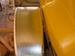
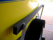
Between a tire and a hard hull

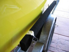
Side view with the bunk carpeting installed

As for the height, I simply measured that of the original fenders above the tires, and used said measurement for the wider substitutes, giving them the same amount of free space above the tire to accommodate the up-and-down movement of the suspension, as seen above in the photo on the right, with the bunk carpeting installed along the top.
That bunk carpeting, by the way, also extends about an inch below the edge of the fenders on the inside, similar to what International Marine did with a smaller strip of carpeting on the original fenders. This is so that, should the hull ever push past the guide bunks and strike the fender, the carpeting will protect it from scrapes and gouges on the metal. You can see that such is the case in the photos below. The one on the left shows the finished product, with a piece of non-skid material trimmed and glued to the step. On the right is a close-up that shows the gap between the hull and the fender.

Finished Product

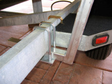
Close up of the gaps

Carpeted Guide Bunks Over Wheels

Installing guide bunks along the sides of the trailer was one of the first upgrades I wanted to add to Harried Potter. Not only would the guides keep the boat properly centered so that it wouldn’t shift against the fenders or wheels while on the highway, they would also make it much easier to “shoehorn” the boat onto the trailer when retrieving her at the launching ramp.
I went to West Marine and purchased a set of 5' guide bunks. When I attempted to install them, however, I found that they were inadequate to accommodate the particular shape of a P-19 and the Pacific Baja trailer.
Specifically, the crossbeams on the trailer frame are located too far forward and aft to mount the bunks at the widest part of the hull. Moreover, the side beams are too far to the outside. West Marine’s bunks are supposed to be adjustable for different widths, but there is a limit to how close one can get the mounting poles to the trailer before their shape no longer is square enough along the angled curve for the hardware to secure them tightly, as illustrated in the photo below.

West Marine’s bent mounts

As a result, I found to my chagrin that there was still a rather large gap between the boat hull and the bunk boards, as in the photo below. While they might still function well as “guides,” they nonetheless would not prevent the boat from shifting sideways on the trailer.

West Marine’s guide bunks

Other P-19 owners suggested mounting additional “spacer” boards behind the bunks to move them closer to the inside. This would probably work, but I do not think that I would be very happy with the æsthetics of that solution, as it would look somewhat “patched” together, as though the bunks do not really fit the boat —which, of course, they do not. I therefore took my set of bunk boards back to West Marine for a refund and started to look for other alternatives.
The West Wight Potter manufacturer, International Marine, came to the rescue. They contacted their new trailer supplier, EZ Loader, and found that they manufacture 6' guide bunks that can be mounted closer to the trailer. They work!
International Marine subsequently obtained a number of those EZ Loader guide bunks for P-19 owners to purchase at a significantly discounted price and I immediately ordered a set. They said that they would arrive in 1-2 weeks, but I received them only five days later.
The difference between these bunk boards and those from West Marine is evident. Rather than “bent” mounts, EZ Loader uses a welded frame so that the horizontal bar remains square all the way up to the vertical bar. It is therefore possible to slide the mounts as close to the boat as needed, as shown in the photo below.

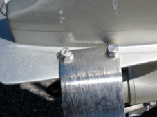
EZ Loader’s welded mounts

I decided to install my set with the mounts just beyond the fender steps fore and aft, so that the inner edge of the swivel brackets are about 12.5" from the ends of the boards. I also decided to slightly angle the boards inward at the front to help center Harried Potter when retrieving her at the ramp. To form that very slight angle, I slid the rear pole about 3.5" out from the trailer frame, and the forward pole about 2" out from the frame.
In this position, the middle of the guide board is snug against the hull, as shown below, directly above the fender. When the trailer is in the water at the launching ramp, the bunks are still visible, slightly above the water, which makes it much easier to aim Harried Potter correctly onto the trailer when retrieving her.
You’ve got to hand it to International Marine. They always go the extra mile to help P-19 owners upgrade their boats with the best accessories available.

EZ Loader’s guide bunks

Custom Bow Light Pedestal

Our P-19 has a custom stainless steel anchor roller on her bow in lieu of the standard mount hanging off the pulpit. The anchor itself is a bruce model, touted by some as one of the most effective. The entire accessory is a solid piece of work, very similar to the setups you will see on much larger vessels. I am very pleased with it.
There was just one problem with this anchor roller. Since it was mounted on the very front of the bow, and was several inches high, the standard navigation light on the boat was no longer visible from the port side, as you can see in the photo below. Unless and until I could find a solution, I could not have Harried Potter out on the water after sunset.

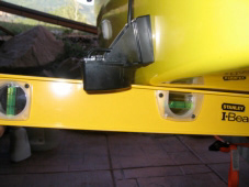
The anchor roller eclipses the bow lights

At first I thought that I would have to mount a navigation light on the bow pulpit, thus switching the anchor and light positions that International Marine had originally designated when building the boat. I know that other Potter owners have done this, somehow feeding the light’s wires up through the rails themselves. Then I ran across another alternative: navigation lights on poles specifically designed to raise them above anchor rollers and other deck hardware. The most promising designs were from Perko.
I ordered a round, vertical base with a locking collar which had the same dimensions as the standard Perko light that I was removing. The base fit very well, and included a small rubber stopper on a flap with which to cap the base when not in use. You can see the capped base in the photo below.

The new base with its cap closed

The pole that I ordered was the 12" model, also with a locking collar. I was intrigued to see the simplicity of this type of connection. The plastic around the bottom is simply off-center, i.e., one side is fatter than the other. When you rotate the plastic, the fat side on the pole pushes against the similarly fat wall of the base and the light is “lodged” into place with its electrical connections lined up properly.
Of course, it is only necessary to mount the pole light after dark: the rest of the time it is safely stored inside the anchor locker with the rode and chain, within easy reach. In the photo below you can see what the pole light looks like when stuck into its base. The most important point is that this pole light does the job. Harried Potter’s bow lights are now visible on both her port and starboard sides, despite the bulky anchor roller on her bow.

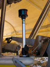
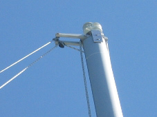
The pole light rises to the occasion

36 Quart Cooler Gangway Step

To climb in and out of the cabin in a P-19 is a big step, and difficult to do gracefully because of the bottom lip of the gangway. Consequently, many owners purchase small step ladders that mount in the same holes as the v-berth dining table. However, I decided that such an accessory should serve a double duty. Rather than merely install a ladder, I decided to purchase another 36 quart Igloo ice chest identical to the one under the v-berth, and build a holder for it to function as a step.
There was a method to my madness. Because the height of the ice chest and that of the cockpit floor are practically the same, it provides a level surface to stand upon when moving from one area of the boat to the other. And there was an added benefit: no longer would it be necessary to go digging under the v-berth to get snacks and drinks while out on the water: one simply had to reach in, open the lid, and grab whatever struck one’s fancy. In fact, having the ice chest so readily available also makes cooking on the stove easier and more convenient. And the ice chest is less obtrusive than a set of steps: one can still use the dinette table and seats when settled in for the night without removing it.
I decided to construct a holding box for the ice chest out of plywood the same thickness as our v-berth filler board/dinette table. I cut a flat floor piece and four rather short side pieces that were only as tall as the beveled bottom of the ice chest. Using wood screws, I purposely mounted these side panels to each other and the floor board so that said lower portion of the ice chest would fit tightly inside the box, giving the entire structure a square shape —rather than tapered to the inside.
I then mounted the box on a 2x3 board running lengthwise from the back wall to the centerboard trunk along the bottom dip in the floor, being careful to position it far enough forward on this beam to allow the ice chest lid to swing open and back freely on its hinges. Next, I cut a couple of angled notches at the rear end of the 2x3 board so that any water could still run through the drain hole into the bilge area. Finally, I bolstered the front and back of the box with small triangles of wood to further transfer any weight on the ice chest’s edges outwards. Below is a photo of what the box looks like when empty, after I had sanded, stained, and varnished it.
Once I put everything together, it looked better than I expected, almost as if the boat had been designed to accommodate such a step. You can see the result below and judge for yourself. We also discovered another unanticipated feature. There was now an empty, hidden storage area behind the step and under the cockpit. We decided to use it... as a dirty clothes hamper.

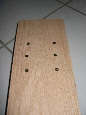
The box to stablize the ice chest step

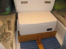
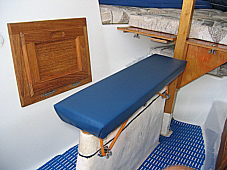
With the ice chest step installed

Auto Pilot Upgrade

Harried Potter came with a tiller tamer, but those helm “clamps” cannot maintain consistent tacks for very long if a skipper needs to take care of complicated tasks like setting lines, furling the lapper, raising or lowering the bimini, etc. Consequently, an autotiller is one of the most useful accessories one can install on a sailboat, especially if ever planning on sailing single-handed.
It is also one of the most expensive. The model often found on vessels our size is the Raymarine Autohelm Series ST1000 Plus, available from West Marine. In my case, however, I ordered one from International Marine, as I like to be supportive of my boat’s manufacturer Happily, they let me have the ST1000 Plus for the same price as West Marine. They also sold me an extension arm, as they said it was necessary on a P-19 —and they were right!
The first question I had to ask myself is where to install the ST1000 Plus.I called International Marine to find out where they install the ST1000 Plus on a P-19. Their reply was that they always mount it in the middle of the gunwale, hence the need for the extension arm to reach the tiller. They also suggested measurements to a spot between the rear of the transom and the cockpit rails. However, the eye-hook for our bimini already occupied said location. After a great deal of perseveration and measuring, I decided that the best I could do was install the autotiller a bit further back, between that eye-hook and the rear cleat, just far enough from the latter for a rope to fit through, and just far enough from the former that the autotiller wouldn’t interfer with the bimini strap. You can see the location in the first photo below.

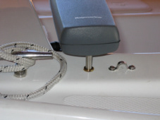
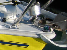
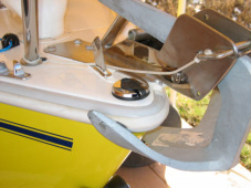
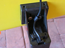
Where I installed the autotiller

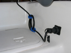
Location of the plug

The second installation step was to mount the plug fixture and run its wiring to the boat‘s electricity. This also took a fair amount of contemplation and measuring. The plug for the autotiller sticks out a couple of inches, and you certainly wouldn’t want it intruding into the sitting area. In my case, neither did I want it getting in the way of the cockpit seat hatches mentioned above. I finally determined that the best possible place to mount the plug on our boat would be on the back wall, underneath where the autotiller itself was located, far enough from the side to take advantage of the transom’s curve for the needed distance from the hatch, yet not so far that it would end up intruding into the glove box inside or interfere with the winch handle. The photo above shows this location, and how its wire runs along the edge of the seat, still allowing access to the starboard hatch.
The final step to complete the installation was to mount the tiller bracket onto which the autotiller connects. This was probably the easiest task of the entire process. The only real problem was to make sure I mounted it far enough out on the underside of the tiller that it would not strike the cam cleat for the mainsheet, as seen below.

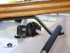
The tiller bracket clears the cam cleat

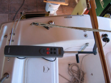
Bird’s eye view of the installed autopilot

The autotiller works extremely well, better than I would have expected. Once you set your heading, the mechanism constantly pushes and pulls the tiller back and forth to keep you moving in the same direction, no matter the shifts, gusts, or velocity of the wind. It is truly a joy to be able to let the autotiller do the work in those instances when you have to, say, get a fender or rope out of a hatch, retrim the sails, untangle a sheet, duck inside the cabin to grab a drink, a snack, a tool, a jacket, a camera, etc.
In summary, the autotiller really is one of the best accessories available for a P-19. I would highly recommend to anyone who sails, especially single-handed. It is worth the extra money invested.
Custom Mast Topping Lift

In my humble opinion, a topping lift —or a boomkicker— is more a necessity than an option. You need to be able to easily raise, lower, and secure the aft end of the boom to set up a bimini, take in a reef, or achieve the optimal mainsail shape depending upon the wind and direction. I can’t imagine trying to set or dowse the sails without one. I even find it useful when rigging and de-rigging the boat, as it helps hold the end of the boom up as I move it in and out of the cabin or insert and remove the sail slugs.
The standard topping lift on a P-19 works well enough, but has one glaring flaw: it feeds through a single pulley at the top of the mast. Consequently, when the mainsail is fully raised, its outmost edge will chafe against the topping lift’s line when you tack or jibe. Eventually said chafing could cause some damage.
I decided to remedy that potential problem by installing a second pulley at the end of the small extension arm for the backstay at the top of the mast. Fortunately, there is plenty of room on itssmall crossbeam to accommodate both the cable and a pulley, as you can see in the photo below.

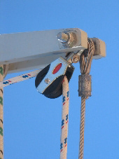
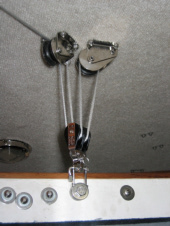
Adding a pulley to the backstay extension

The line fed through both pulleys

In the photo above, you can see how the topping lift’s line now feeds through both pulleys, thus extending it almost as far away from the mast as the backstay. I purposely used a pulley with a swivel mount so that it can rotate easily when the line is drawn taut.
When you connect the topping lift to the boom, the line will now form its angle downwards at a point further away from the mast, as seen in the following photo.

The line angle when attached to the boom

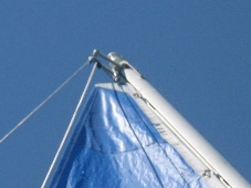
The line no longer chafes the mainsail

The photo above shows that this small amount of distance is all that is needed so that the mainsail no longer strikes against the line. In my opinion, the price of the extra pulley is a minimal amount to pay to save the mainsail from unnecessary wear-and-tear.
Custom Prop Guard

One of the first accessories that I looked into for our P-19 was some sort of propellor protector. I wanted to shield our rudder from the prop, in case the bottom half were inadvertently raised and then turned toward the outboard. I also wanted to protect the blades from dirt, rocks, and ramps. More importantly, however, I wanted to protect any living organism that happened to be in the water when I motored by. For the life of me, I can't imagine why all props do not come with such a guard: can you imagine the havoc those blades could wreak on an arm, a leg, a head, a paw, a fin? What are the manufacturers of marine engines thinking, anyway?
I found several propellor protectors on the web, and for an equally disparate range of prices. International Marine had noted my posts asking about these accessories in the Potter forum, and dropped me a note to give (in his words) “a shameless plug” for a stainless steel prop guard that they themselves build in their machine shop. Practically identical to Cabela’s Prop Saver, their homemade version cost at least $30 less. I would rather be supportive of my boat’s manufacturer anyway, so I ordered one of their Propellor Guards.
The package arrived within a couple of days, complete with mounting hardware and a one-page instruction sheet to install the guard. I noted that the bolts seemed unnecessarily long for my motor. I therefore took them to our local hardware store and bought some shorter equivalents, just long enough to reach through to the nylon nuts securely.
I could immediately see that I would have no problem mounting this prop guard on the Honda outboard, as it was designed to fit along the skeg's side and above its bottom bulb. I measured all the holes three times and drilled once. You can see how the guard attached to the skeg in the photo below.

Mounted to the skeg

Mounted to the cavilation plate

Likewise, in the photo above you can see how the prop guard attached to the cavilation plate. The instructions specified that I should place the guard over the top of the plate and insert the bolts from the bottom up. I am fairly sure that other Potter owners do just the opposite when they mount this same guard, putting it under the plate and inserting the bolts from above, but I suppose that they know what they are doing at the factory. I followed their instructions to the letter.
There was just only one particular detail that their sheet didn’t address: what to do with the anode, since it was also sitting on top of the cavilation plate. I decided that, instead of removing it entirely, I would file about 1/2" off its front end to accommodate the prop guard. In the photo below you can see that the anode is still on top of the port side of the plate.​​​​​​​

The Prop Guard on the Honda 5hp Outboard

In short, International Marine’s prop guard fits well and is extremely solid. I doubt that any conceivable blow underwater could dent it. Some manufacturers claim that these guards can increase the motor’s power and speed, but I haven't noticed any such improvements in the Honda’s performance since installing it. Of course, that’s not really why I got it. At least now I need not worry about damaging my rudder, nor the prop itself —nor any manatee that happens to swimming near a shoreline!
Daggerboard Winch system

The P-19 daggerboard winch system works very well, allowing the person at the helm to raise and lower it from rear of the cockpit via a system of pulleys into the cabin. However, as shown in the photo below, its standard wire cable can become twisted, frayed, and eventually unravel enough to even break. For this reason, I decided upgrade the system with a better alternative: Amsteel Dyneema Single Braid. It is more expensive than other high-strength lines, but also has a superior tensile limit of 2,500 lbs. I actually bought enough for two winch systems: one that is in use, and another as a backup spare —just in case.

Typical damage to a wire cable

I also decided to replace the standard housing with a Harken double-pulley no. 084 and a Ronstan keypin locking shackle. The extra pulley in the winch system makes it easier to crank the daggerboard up. As for the shackle, it allows one to detach that double-pulley and crank it up to the ceiling so that the winch line is completely out of the way when on the water.
Below is a photo of the Amsteel line fed through all the pulleys; beneath is a close-up of the double-pulley and shackle. The results are a vast improvement: the winch system is quieter without the grinding wire cable, and easier to crank with the double pulley. The Amsteel is amazingly strong: I doubt that backup spool of line will ever be necessary. It is also great to being able to detach the shackle and raise the winch line while on the water, making it much easier to move about the cabin.

The high-strength line

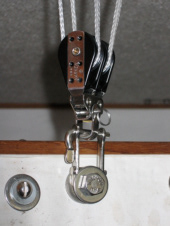
The double-pulley and shackle

Depth Transponder Upgrade

The first challenge with this upgrade was to determine exactly where to mount the transponder. International Marine told me that they install them all the way over by the swim ladder. This puzzled me, as I assumed I should try to position the transponder as close to the boat’s centerline as possible. Upon examining the transom more closely, however, I saw the method to International Marine’s madness: any closer to the centerline and the rudder would strike the transponder when turning hard over to starboard. I therefore settled on a spot just beyond where the rudder might hit, as illustrated in the photo below.

Positioned so the rudder doesn’t strike it

Slight upward angle in relation to hull

The next challenge was to determine the proper angle for the transponder. The instruction booklet is surprisingly specific about this. It states that the transponder must be slightly tipped so that the front is no more than 1/8" higher than the back. At first, I mistakenly thought that the angle was in relation to what is “level,” but then I realized it is supposed to be in relation to the hull itself. Above, in the photo, I have placed my level flat against the bottom of the hull, and you can see how the transponder is, in fact, slightly angled upwards towards the front. This is apparently so that bubbles and turbulence do not thwart the unit’s ability to send, receive, and interpret its sonar signals as the water comes flowing underneath the hull and across the bottom of the transponder. To achieve this angle, I had to insert behind the mounting bracket the additional 4° shim that comes with the transponder.
The instructions also state that the bottom of the transponder must be no more than 1/8" below the hull. This proved a bit more problematic, because a P-19’s hull is not flat, but rather angles up sideways from the skeg to the outside of the boat. I decided that the only solution was to mount the transponder a little deeper on the right, and a little shallower on the left, with the hope that an “average” of 1/8" below the hull would suffice.
The transponder came with two clamps and a through-the-hull fixture for threading its wire up the transom and into the boat. However, I did not like the way the wire exits the unit so far away from the boat: it would be very easy to accidently hook that wire with an errant toe or finger when climbing up or down the swim ladder. I therefore decided to install one of the clamps directly to the mounting bracket itself so that the wire was bent closer to the transom, as shown in the first photo below. In the second photo below, you can see the second clamp, screwed to the transom, about halfway up to where the wire enters into the boat.

First wire clamp on the mounting bracket

Second wire clamp halfway up

The instruction booklet states that the wire should enter the transom at a spot “well above the waterline.” I decided that the best spot would be at the same level where the swim ladder’s bottom bolts enter the transom, which is more than a foot above the waterline, but not too much in the way of anyone actually using the ladder. You can see that spot in the photo below:

The finished installation on the transom

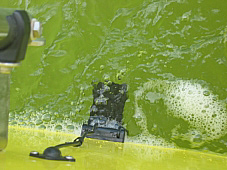
The depth sounder actually works!

Now came the test. Would the transponder really work? I towed Harried Potter to my local pond, rigged and launched her, and set out on the water. Above you can see the transponder from above, with bubbles and turbulence swirling around the transom —more than I ever realized was back there.
I must have installed the transponder at just the right angle because, despite that turbulence, the depth sounder works! You can see that its display is functioning in the photo below. It updates the trandsucer’s readings every second, even as the boat bobs up (deeper) and down (shallower) on the waves.​​​​​​​
Once in a while, depending on conditions, the unit can’t get an accurate reading and temporarily displays three dashes ( - - - ) instead of the depth. I have found that this is more likely to occur if the boat is moving very slowly, and heeling to port, since that scenario can generate more froth around the transponder than when either sailing at a decent speed or stuck in doldrums. Regardless, if I simply wait a few seconds, a depth reading will again appear.
In my opinion, a depth transponder is essential in a sailboat, since a keel or daggerboard is always much lower in the water than one might assume from the way a hull looks on the water. A nice feature of this unit is that one can set it to sound an alarm when the bottom starts to get too shallow. I would often configure that setting at 8-to-10 feet, about twice as deep as a P-19’s daggerboard.
Solution to Drain the Sink’s Water Bladder

Potter owners often scratch their heads over how to drain the sink’s water bladder. Surely there must be a better way than pumping the tiny faucet lever for at least a half hour to empty the water down the sink’s drain! Consequently, some owners will unscrew the plug on the rear skeg, undo the clamps for the bladder’s hoses, and letthe water run through the bottom of the boat and out the transom. Frankly, that idea doesn’t thrill me much. In the first place, it would wear-and-tear those clamps and hoses when constantly loosening and tightening them, especially when struggling with the necessary tools inside the very cramped quarters of the sink’s cupboard. In the second place, dumping water into the bottom on the P-19, soaking the fiberglass and possibly spawning mold and mildew is not a good idea. Water is supposed to stay out of a boat, isn’t it?
I therefore came up with what I consider a much better solution: using a drill pump like the one illustrated below. I found at Home Depot this particular Flotec model (FPDMP21SA), but there are many other brands available.

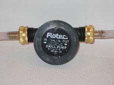
The Flotec drill pump

Pumping the water down the drain

As you can see above, in addition to the drill pump, I also bought a couple of female hose connectors that reduce down to 1/2" male ends. I then bought about one foot of clear plastic tubing with a 3/8" internal diameter. I cut the tube into two pieces and inserted them over the connectors. To drain the bladder, I move the faucet’s pump lever back to its “open” position, put the “in” hose over its spigot, the “out” hose down the drain, attach the pump to my drill, press its trigger, and —voilà!— it sucks the water out. You can see how it all works in the second photo above.
It takes me about 5 minutes to completely drain the bladder. If one has a battery-powered, rechargable drill, it would even be possible to drain the water bladder when retrieving the boat at the ramp when no electrical outlet is available.
Bungee Tie-Down for Daggerboard

I am willing to bet that practically anyone who contemplates for the first time the bolts and wing nuts that hold down the daggerboard on a P-19 would react with bewilderment and even a bit of fright. The way those bolts stick out at an angle, right at shin’s height, strikes one as a painful boo-boo just waiting to happen.
However, there is a method to International Marine’s madness. Those bolts are purposely mounted at an angle so that, if the daggerboard ever bottoms out, the impact will not only be directed up and back, but also diagonally, popping out the hardware’s tiny screws. Otherwise, such a collision could do serious damage to the daggerboard’s trunk. If and when such a mishap occurs, you are supposed to re-epoxy the stripped screw holes and re-mount the hardware.
Maybe I am too lazy, but having to re-epoxy and re-mount that hardware in such instances does not appeal to me. I have no expertise when it comes to working with fiberglass and would probably screw the job up (pun intended). I determined to come up with a better way of securing the daggerboard when it was down.
I decided to remove the International Marine’s upper hardware with the bolts and wingnuts, but leave the bottom pieces with the little double hooks on the trunk itself. My idea was to use them to string an industrial-strength bungee cord over the daggerboard. I had such a bungee on hand, 3/8" thick and 3 feet long, just enough when stretched to wind it around those hooks in the pattern illustrated to the right, steps 1 to 4, as seen from above looking down:

Suggested pattern to stretch a bungee among the hooks

The bungee criss-crosses the daggerboard four times, thus nearly quadrupling its holding strength. It goes straight over both ends (probably where the security most matters) and crosses in the middle (still allowing me to use my releasable double-pulley). Most important of all, the bungee will likely “give” somewhat if and when the daggerboard ever strikes bottom, thus protecting the trunk from structural damage.
Below is a photo in which you can see my bungee on the daggerboard cap. I have used it ever since, and one afternoon was able to put the system to the test while at Lake Powell. We sailed to the far end of Bullfrog Basin, turned around, and were heading back when we heard a muffled thump, and the boat started to slow down. I immediately looked in the cabin at the daggerboard, and —sure enough— it was pushing out of the trunk, with the bungee stretching up about 8 inches on the back and 4 on the front. Obviously, we had struck a sandbar and the bungee effectively “dampened” the impact, but without breaking any hardware —as would have occurred with the original bolts and wingnuts.
As to whether the bungee would hold the daggerboard within the trunk if turtled, I confess that I haven’t tested out that scenario —and never hope to! Nonetheless, I have looked up the tensile strength of bungees on the web. A 3/8" bungee like this one has a tensile strength of 400 lbs. Since the bungee criss-crosses the daggerboard four times, that would suggest a theoretical breaking limit of: 4 x 375 = 1,500 lbs.
On the other hand, we know that knots reduce the tensile strength of line, so I assume that winding the bungee around the trunk’s lower hooks might do the same. For argument’s sake, let’s assume that it even reduces the breaking limit by as much as half: 1,500 x 50% = 750 lbs. That is still more than twice the weight of the 300 lb. daggerboard. I therefore have a hard time imagining that it could fall down (up) to the ceiling if the boat turned turtle, so one need not worry about that ever happening.

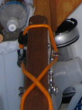
Bungee cord on the daggerboard

Daggerboard Bench Seat

I had already improved the daggerboard winch system so that we could remove its line entirely while on the water. I had also replaced the angled t-bolts and wing-nuts with a thick bungee cord. Now I could focus on trying to make the trunk a more desirable feature of the cabin rather than an inconvenient intrusion.
I am willing to bet that every owner of P-19s has sat on the daggerboard trunk at one time or another, most likely while scrounging around in the cupboards or cooking on the stove. Unfortunately, one’s gluteus maximus can withstand its narrow wooden board just so long. Obviously, what is sorely needed (pun intended) is some kind of cushioned, removable “cap” that would temporarily convert the trunk into a small bench seat.
After carefully measuring the dimensions I would need, I went to Home Depot and bought some wood screws, a 1"x8"x2' oak board, and a matching 1"x2"x2' molding strip. I cut the latter piece into four “braces” to mount on the underside of the larger board. I used my dremel’s sander to round off the boards’ sharp corners and also to hollow out some grooves underneath to fit over the bungee cord and some of bolts and nuts. On the left below you can see the wood screws on the top of one end of the board; on the right you can see the molding underneath and a few of the grooves.

The board from above

The board from below

I then cut out a 2'x8" piece from an old So-Pac foam cushion that I had lying around to use as a pad. After staining and varnishing the underside of the board, I glued the pad onto its top with the same 3M 77 Multipurpose Adhesive that I had used to install marine carpeting on the fenders of the boat trailer. Below you can see the finished result when it is off of the daggerboard trunk.

The bench seat underneath

The bench seat on the trunk

Next, to make the seat more attractive, I needed to cover it with some kind of upholstery. I decided to use vinyl because it is more water-repellant, something well worth consideration in a sailboat. Also, it doesn’t get as dirty as cloth and is easier to clean. Finally, I seriously doubted that I could find a piece of cloth that would match the cabin cushions, but I could find vinyl the same color as the Mediterranean Blue Sunbrella used on our bimini, sail cover, cockpit cushions, rail pads, etc. I trimmed off a piece of the vinyl to stretch over the seat’s foam and underneath the wooden board. I then tacked the vinyl down underneath using my staple gun. The staples actually look better than I thought. Above you can see how the bench seat looks when placed over the daggerboard trunk.
I am happier with this upgrade than I would have thought. I really appreciate that, since the P-19 doesn't have full standing room at the galley, sitting on the daggerboard bench seat makes all the difference in the world when fixing meals, with the cupboards, sink, stove, and cooler step all within easy reach.
Back to Top